
First, a little backstory
Like many other builders here I grew up watching Battlebots/ Robot Wars and was like yaaaaas that is too cool. One robot I loved to watch was (in a Mark Beiro voice) Weeeedge oooof Dooooooooomm.

Another robot that interested me was this guy: Gammaaaa Raptoooor
Gamma Raptor here bore many similarities to Wedge of Doom in the fact that they are both really speedy lifter lightweights. So you can imagine how hyped I got when I saw this fight.
Their respective designs were both very similar to each other, but they had differences that I liked about one versus the other. Wedge of Doom had a greater range of lift-a-bility than Gamma Raptor due to it having a 180 degree arc shape versus the 4-bar lifter of Gamma Raptor which had a smaller range of motion. However, Gamma Raptor's shape was much tighter and the close proximity of the wheels to one another made turning great. Additionally, the wheels poking out so cleanly allows it self-right even when it is stuck.
I loved them both tho so like the commercial says I just fused them. Note: there were two other versions of WoD preceding this one (hence the v3) but I'll probably just put that in a Servo article :P
Now, onto the build!

So in this blurry phone picture we make out that the first of the frame rails has at least been cut out.

In this not so blurry pic we see that this robot has integrated notches built into it. The goal of these notches (besides looking legit) is to strengthen the front wedges. When the front wedges have notches cut into them, they will overlap each other much like a jigsaw puzzle. By overlapping this way, a large portion of the energy from a weapon shot will be transmitted away from the screws and into the 5/16" 7075 Aluminum which is considerably stronger and will therefore absorb the energy better.

At this point, I had begun to cut the blank 1/8" holes into the top of the frame rails in order to prepare to tap them for 6-32 screws to attach the top and bottom plates.

I done goofed up that one. That was most of the tap breaking off in the hole because I sneezed as I was removing it (sigh). As a result, I had to make another hole directly behind it. The other whole is fine, but now I'm down like half of the tap.

Here is the fix happening in the drill press.

First screw in!

So here is the first part of a pretendo-bot frame. This is basically just the cross brace and the left frame rails shoved together. That interlocking bit took some time, but it is a fairly tight fit which is good so as much energy as possible is translated


A look inside of the chassis (note the motors and wheel attached). Now those motors are a little different than average 1000RPM Motors because they are mated to Banebots 370 sized motors. They are considerably faster than the usual motors and they all have metal back which makes it less easy to ruin by heating it too long. On 3s they are already blistering so with a 4s it should be lightning quick. For a non-high KE robot, a speedy drivetrain is super important as it allows it to still be entertaining as well as more maneuverable.

Still on weight!

Better pretendo-bot with the top/bottom plates on


Example of the counter-sunken holes in the frame rail

Even more pretendo-pretendo bot

Getting ready to battle some .06" Grade 5 Titanium with some fancy McMaster cut-off wheels thanks to Charles Guan.

Well, they came out looking nice, but I messed up the left one by leaving it a liiitle too short. Welp, guess you measure twice then cut once..

So this is a side flap and was planning on bending it down to cut the sides. I even cut a little groove along the bend to make it easier. Unfortunately, I forgot that titanium (with the exception of really thin material) needs heat to bend...

....so I ended up just breaking it off and smoothing it off.

Here is an example of the "notch method" from earlier. A vertical or horizontal shot to the wedge is transferred to the frame rail and vice versa. This should help keep it strong against those meenies.

Not bad, right? Kinda? Okay I admit that they aren't perrrrfect but considering 90% of this was hand tools it was pretty good.

Fingertech Robotics belts and Tiny Switch!

The belts are on! Its almost-not-quite-okay-not robot fighting time!

From da rear. From here the motors are clearly seen.

Some early wiring done to the drive ESCs and motors. Those black drive ESCs are Vextroller 29s which can be hacked and then used for drive. However, they don't have an internal Battery Eliminator Circuit (BEC) which powers the receiver and power the servo (which comes from the receiver). In this case I'm using a Castle BEC.

Yay its still on weight!

I did some work on the lifter frame rails by cutting them out of some Alum and then pressing the bushings into them. They provide a very smooth lifting action and doesn't lose much energy to lift.

Rewired with the switch and servo mounted. That servo is a Savox 1231SG servo which has more than enough power to lift a 3lber up all the way off the ground.

Closer to completion. Note: That wrench is not a weapon but instead turns the robot on and off.

Tiiii wings! They were designed to both strengthen the outer frame rails against horizontal hits as well as keep it from getting stuck on its side. Unfortunately, they ended up messing with the drive as they messed up the belt's tension and therefore would ruin drive. Also in the picture is rear mounting blocks for the lifter. Nothing special; just two blocks of aluminum with a spacer in between.

The arm linkage is in place! Too bad the arms don't mesh perfectly..

Solution? offset the screws so the arm still remains level!

Here are some spacers I attempted to use as tensioners, but they ended up having the same effect as the tii wings strangely enough. Oh well, just gonna have to make do with what I can.

At this point, when half the robot is apart on the floor, did I realize this miscalculation (facepalms)

The rear end is finally attached! It is made some of the 1/8" UHMW armor from the original Play'n Krazy and the Weta kits.
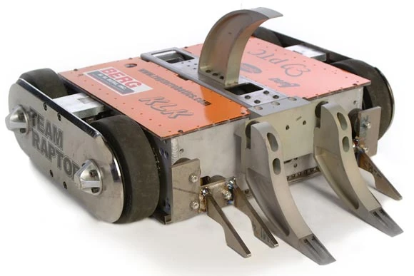
And that's a wrap on WoD v3!


